
5. PlutoSDR in Python
In this chapter we learn how to use the Python API for the PlutoSDR, which is a low-cost SDR from Analog Devices. We will cover the PlutoSDR install steps to get the drivers/software running, and then discuss transmitting and receiving with the PlutoSDR in Python. Lastly, we show how to use Maia SDR and IQEngine to turn the PlutoSDR into a powerful spectrum analyzer!
Overview of the PlutoSDR
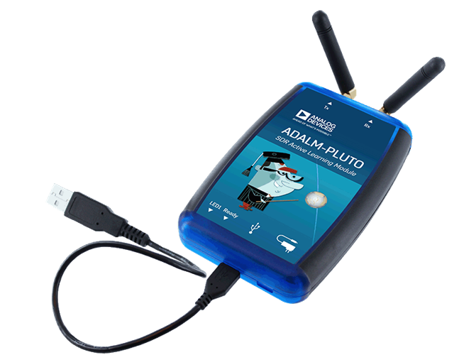
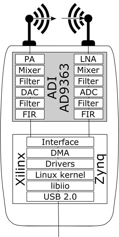
The PlutoSDR (a.k.a. ADALM-PLUTO) is a low-cost SDR (just over $200) that is capable of transmitting and receiving signals from 70 MHz to 6 GHz. It is a great SDR for those who have outgrown the $20 RTL-SDR. The Pluto uses a USB 2.0 interface, which limits the sample rate to around 5 MHz if you want to receive 100% of samples over time. That being said, it can sample up to 61 MHz and you can capture contiguous bursts up to around 10M samples long at a time, allowing the Pluto to capture an enormous amount of spectrum at once. It is technically a 2x2 devices, but the second transmit and receive channels are only accessible through U.FL connectors inside the case, and they share the same oscillators so you can’t receive on two different frequencies at once. Below shows the block diagram of the Pluto, as well as the AD936x which is the RF integrated circuit (RFIC) inside the Pluto.

Software/Drivers Install
Setting up VM
While the Python code provided in this textbook should work under Windows, Mac, and Linux, the install instructions below are specific to Ubuntu 22. If you have trouble installing the software on your OS following the instructions provided by Analog Devices, I recommend installing an Ubuntu 22 VM and trying the instructions below. Alternatively, if you’re on Windows 11, Windows Subsystem for Linux (WSL) using Ubuntu 22 tends to run fairly well and supports graphics out-of-the-box.
Install and open VirtualBox.
Create a new VM. For memory size, I recommend using 50% of your computer’s RAM.
Create the virtual hard disk, choose VDI, and dynamically allocate size. 15 GB should be enough. If you want to be really safe you can use more.
Download Ubuntu 22 Desktop .iso- https://ubuntu.com/download/desktop
Start the VM. It will ask you for installation media. Choose the Ubuntu 22 desktop .iso file. Choose “install ubuntu”, use default options, and a pop up will warn you about the changes you are about to make. Hit continue. Choose name/password and then wait for the VM to finish initializing. After finishing the VM will restart, but you should power off the VM after the restart.
Go into the VM settings (the gear icon).
Under system > processor > choose at least 3 CPUs. If you have an actual video card then in display > video memory > choose something much higher.
Start up your VM.
I recommend installing VM guest additions. Within the VM go to Devices > Insert Guest Additions CD > hit run when a box pops up. Follow the instructions. Restart the VM. The shared clipboard can be enabled through Devices > Shared Clipboard > Bidirectional.
Connecting PlutoSDR
If running OSX, within OSX, not the VM, in system preferences, enable “kernel extensions”. Then install HoRNDIS (you may need to reboot after).
If running Windows, install this driver: https://github.com/analogdevicesinc/plutosdr-m2k-drivers-win/releases/download/v0.7/PlutoSDR-M2k-USB-Drivers.exe
If running Linux you shouldn’t have to do anything special.
Plug Pluto into the host machine over USB. Make sure to use the middle USB port on Pluto because the other is for power only. Plugging in Pluto should create a virtual network adapter, i.e., the Pluto appears like a USB ethernet adapter.
On the host machine (not VM), open a terminal or your preferred ping tool and ping 192.168.2.1. If that doesn’t work, stop and debug the network interface.
Within the VM, open a new terminal
Ping 192.168.2.1. If that doesn’t work stop here and debug. While pinging, unplug your Pluto and make sure the pinging stalls out, if it keeps pinging then something else at that IP address is on the network, and you’ll have to change the IP of the Pluto (or other device) before moving on.
Write down the IP address of the Pluto because you’ll need it when we start using the Pluto in Python.
Installing PlutoSDR Driver
The terminal commands below should build and install the latest version of:
libiio, Analog Device’s “cross-platform” library for interfacing hardware
libad9361-iio, AD9361 is the specific RF chip inside the PlutoSDR
pyadi-iio, the Pluto’s Python API, this is our end goal, but it depends on the previous two libraries
sudo apt-get install build-essential git libxml2-dev bison flex libcdk5-dev cmake python3-pip libusb-1.0-0-dev libavahi-client-dev libavahi-common-dev libaio-dev
cd ~
git clone --branch v0.23 https://github.com/analogdevicesinc/libiio.git
cd libiio
mkdir build
cd build
cmake -DPYTHON_BINDINGS=ON ..
make -j$(nproc)
sudo make install
sudo ldconfig

cd ~
git clone https://github.com/analogdevicesinc/libad9361-iio.git
cd libad9361-iio
mkdir build
cd build
cmake ..
make -j$(nproc)
sudo make install

cd ~
git clone --branch v0.0.14 https://github.com/analogdevicesinc/pyadi-iio.git
cd pyadi-iio
pip3 install --upgrade pip
pip3 install -r requirements.txt
sudo python3 setup.py install
Testing PlutoSDR Drivers
Open a new terminal (in your VM) and type the following commands:
python3
import adi
sdr = adi.Pluto('ip:192.168.2.1') # or whatever your Pluto's IP is
sdr.sample_rate = int(2.5e6)
sdr.rx()
If you get this far without an error, then continue with the next steps.
Changing Pluto’s IP Address
If for some reason the default IP of 192.168.2.1 does not work because you already have a 192.168.2.0 subnet, or because you want multiple Pluto’s connected at the same time, you can change the IP using these steps:
Edit the config.txt file on the PlutoSDR mass storage device (i.e., the USB-drive looking thing that shows up after you plug in the Pluto). Enter the new IP you want.
Eject the mass storage device (don’t unplug the Pluto!). In Ubuntu 22 there’s an eject symbol next to the PlutoSDR device, when looking at the file explorer.
Wait a few seconds, and then cycle power by unplugging the Pluto and plugging it back in. Go back into the config.txt to determine if your change(s) saved.
Note that this procedure is also used to flash a different firmware image onto the Pluto. For more details see https://wiki.analog.com/university/tools/pluto/users/firmware.
“Hack” PlutoSDR to Increase RF Range
The PlutoSDR’s ship with a limited center frequency range and sampling rate, but the underlying chip is capable of much higher frequencies. Follow these steps to unlock the full frequency range of the chip. Please bear in mind that this process is provided by Analog Devices, thus it is as low risk as you can get. The PlutoSDR’s frequency limitation has to do with Analog Devices “binning” the AD936x chips based on strict performance requirements at the higher frequencies. As SDR enthusiasts and experimenters, we’re not too concerned about said performance requirements.
Time to hack! Open a terminal (either host or VM, doesn’t matter):
The default password is analog
You should see the PlutoSDR welcome screen. You have now SSHed into the ARM CPU on the Pluto itself! If you have a Pluto with firmware version 0.31 or lower, type the following commands in:
fw_setenv attr_name compatible
fw_setenv attr_val ad9364
reboot
And for 0.32 and higher use:
fw_setenv compatible ad9364
reboot
You should now be able to tune up to 6 GHz and down to 70 MHz, not to mention use a sample rate up to 56 MHz! Yay!
Receiving
Sampling using the PlutoSDR’s Python API is straightforward. With any SDR app we know we must tell it the center frequency, sample rate, and gain (or whether to use automatic gain control). There might be other details, but those three parameters are necessary for the SDR to have enough information to receive samples. Some SDRs have a command to tell it to start sampling, while others like the Pluto will start to sample as soon as you initialize it. Once the SDR’s internal buffer fills up, the oldest samples are dropped. All SDR APIs have some sort of “receive samples” function, and for the Pluto it’s rx(), which returns a batch of samples. The specific number of samples per batch is defined by the buffer size set beforehand.
The code below assumes you have the Pluto’s Python API installed. This code initializes the Pluto, sets the sample rate to 1 MHz, sets the center frequency to 100 MHz, and sets the gain to 70 dB with automatic gain control turned off. Note it usually doesn’t matter the order in which you set the center frequency, gain, and sample rate. In the code snippet below, we tell the Pluto that we want it to give us 10,000 samples per call to rx(). We print out the first 10 samples.
import numpy as np
import adi

sample_rate = 1e6 # Hz
center_freq = 100e6 # Hz
num_samps = 10000 # number of samples returned per call to rx()

sdr = adi.Pluto()
sdr.gain_control_mode_chan0 = 'manual'
sdr.rx_hardwaregain_chan0 = 70.0 # dB
sdr.rx_lo = int(center_freq)
sdr.sample_rate = int(sample_rate)
sdr.rx_rf_bandwidth = int(sample_rate) # filter width, just set it to the same as sample rate for now
sdr.rx_buffer_size = num_samps

samples = sdr.rx() # receive samples off Pluto
print(samples[0:10])
For now we aren’t going to do anything interesting with these samples, but the rest of this textbook is filled with Python code that works on IQ samples just like what we received above.
Receive Gain
The Pluto can be configured to either have a fixed receive gain or an automatic one. An automatic gain control (AGC) will automatically adjust the receive gain to maintain a strong signal level (-12dBFS for anyone who is curious). AGC is not to be confused with the analog-to-digital converter (ADC) that digitizes the signal. Technically speaking, AGC is a closed-loop feedback circuit that controls the amplifier’s gain in response to the received signal. Its goal is to maintain a constant output power level despite a varying input power level. Typically, the AGC will adjust the gain to avoid saturating the receiver (i.e., hitting the upper limit of the ADC’s range) while simultaneously allowing the signal to “fill in” as many ADC bits as possible.
The radio-frequency integrated circuit, or RFIC, inside the PlutoSDR has an AGC module with a few different settings. (An RFIC is a chip that functions as a transceiver: it transmits and receives radio waves.) First, note that the receive gain on the Pluto has a range from 0 to 74.5 dB. When in “manual” AGC mode, the AGC is turned off, and you must tell the Pluto what receive gain to use, e.g.:
sdr.gain_control_mode_chan0 = "manual" # turn off AGC
gain = 50.0 # allowable range is 0 to 74.5 dB
sdr.rx_hardwaregain_chan0 = gain # set receive gain
If you want to enable the AGC, you must choose from one of two modes:
sdr.gain_control_mode_chan0 = "slow_attack"sdr.gain_control_mode_chan0 = "fast_attack"
And with AGC enabled you don’t provide a value to rx_hardwaregain_chan0. It will get ignored because the Pluto itself adjusts the gain for the signal. The Pluto has two modes for AGC: fast attack and slow attack, as shown in the code snipped above. The difference between the two is intuitive, if you think about it. Fast attack mode reacts quicker to signals. In other words, the gain value will change faster when the received signal changes level. Adjusting to signal power levels can be important, especially for time-division duplex (TDD) systems that use the same frequency to transmit and receive. Setting the gain control to fast attack mode for this scenario limits signal attenuation. With either mode, if there is no signal present and only noise, the AGC will max out the gain setting; when a signal does show up it will saturate the receiver briefly, until the AGC is able to react and ramp down the gain. You can always check the current gain level in real-time with:
sdr._get_iio_attr('voltage0','hardwaregain', False)
For more details about the Pluto’s AGC, such as how to change the advanced AGC settings, refer to the “RX Gain Control” section of this page.
Transmitting
Before you transmit any signal with your Pluto, make sure to connect a SMA cable between the Pluto’s TX port, and whatever device will be acting as the receiver. It’s important to always start by transmitting over a cable, especially while you are learning how to transmit, to make sure the SDR is behaving how you intend. Always keep your transmit power extremely low, as to not overpower the receiver, since the cable does not attenuate the signal like the wireless channel does. If you own an attenuator (e.g. 30 dB), now would be a good time to use it. If you do not have another SDR or a spectrum analyzer to act as the receiver, in theory you can use the RX port on the same Pluto, but it can get complicated. I would recommend picking up a $10 RTL-SDR to act as the receiving SDR.
Transmitting is very similar to receiving, except instead of telling the SDR to receive a certain number of samples, we will give it a certain number of samples to transmit. Instead of rx_lo we will be setting tx_lo, to specify what carrier frequency to transmit on. The sample rate is shared between the RX and TX, so we will be setting it like normal. A full example of transmitting is shown below, where we generate a sinusoid at +100 kHz, then transmit the complex signal at a carrier frequency of 915 MHz, causing the receiver to see a carrier at 915.1 MHz. There is really no practical reason to do this, we could have just set the center_freq to 915.1e6 and transmitted an array of 1’s, but we wanted to generate complex samples for demonstration purposes.
import numpy as np
import adi

sample_rate = 1e6 # Hz
center_freq = 915e6 # Hz

sdr = adi.Pluto("ip:192.168.2.1")
sdr.sample_rate = int(sample_rate)
sdr.tx_rf_bandwidth = int(sample_rate) # filter cutoff, just set it to the same as sample rate
sdr.tx_lo = int(center_freq)
sdr.tx_hardwaregain_chan0 = -50 # Increase to increase tx power, valid range is -90 to 0 dB

N = 10000 # number of samples to transmit at once
t = np.arange(N)/sample_rate
samples = 0.5*np.exp(2.0j*np.pi*100e3*t) # Simulate a sinusoid of 100 kHz, so it should show up at 915.1 MHz at the receiver
samples *= 2**14 # The PlutoSDR expects samples to be between -2^14 and +2^14, not -1 and +1 like some SDRs

# Transmit our batch of samples 100 times, so it should be 1 second worth of samples total, if USB can keep up
for i in range(100):
    sdr.tx(samples) # transmit the batch of samples once
Here are some notes about this code. First, you want to simulate your IQ samples so that they are between -1 and 1, but then before transmitting them we have to scale by 2^14 due to how Analog Devices implemented the tx() function. If you are not sure what your min/max values are, simply print them out with print(np.min(samples), np.max(samples)) or write an if statement to make sure they never go above 1 or below -1 (assuming that code comes before the 2^14 scaling). As far as transmit gain, the range is -90 to 0 dB, so 0 dB is the highest transmit power. We always want to start at a low transmit power, and then work our way up if needed, so we have the gain set to -50 dB by default which is towards the low end. Don’t simply set it to 0 dB just because your signal is not showing up; there might be something else wrong, and you don’t want to fry your receiver.
Transmitting Samples on Repeat
If you want to continuously transmit the same set of samples on repeat, instead of using a for/while loop within Python like we did above, you can tell the Pluto to do so using just one line:
sdr.tx_cyclic_buffer = True # Enable cyclic buffers
You would then transmit your samples like normal: sdr.tx(samples) just one time, and the Pluto will keep transmitting the signal indefinitely, until the sdr object destructor is called. To change the samples that are being continuously transmitted, you cannot simply call sdr.tx(samples) again with a new set of samples, you have to first call sdr.tx_destroy_buffer(), then call sdr.tx(samples).
Transmitting Over the Air Legally
Countless times I have been asked by students what frequencies they are allowed to transmit on with an antenna (in the United States). The short answer is none, as far as I am aware. Usually when people point to specific regulations that talk about transmit power limits, they are referring to the FCC’s “Title 47, Part 15” (47 CFR 15) regulations. But those are regulations for manufacturers building and selling devices that operate in the ISM bands, and the regulations discuss how they should be tested. A Part 15 device is one where an individual does not need a license to operate the device in whatever spectrum it’s using, but the device itself must be authorized/certified to show they are operating following FCC regulations before they are marketed and sold. The Part 15 regulations do specify maximum transmit and received power levels for the different pieces of spectrum, but none of it actually applies to a person transmitting a signal with an SDR or their home-built radio. The only regulations I could find related to radios that aren’t actually products being sold were specific to operating a low-power AM or FM radio station in the AM/FM bands. There is also a section on “home-built devices”, but it specifically says it doesn’t apply to anything constructed from a kit, and it would be a stretch to say a transmit rig using an SDR is a home-built device. In summary, the FCC regulations aren’t as simple as “you can transmit at these frequencies only below these power levels”, but rather they are a huge set of rules meant for testing and compliance.
Another way to look at it would be to say “well, these aren’t Part 15 devices, but let’s follow the Part 15 rules as if they were”. For the 915 MHz ISM band, the rules are that “The field strength of any emissions radiated within the specified frequency band shall not exceed 500 microvolts/meter at 30 meters. The emission limit in this paragraph is based on measurement instrumentation employing an average detector.” So as you can see, it’s not as simple as a maximum transmit power in watts.
Now, if you have your amateur radio (ham) license, the FCC allows you to use certain bands set aside for amateur radio. There are still guidelines to follow and maximum transmit powers, but at least these numbers are specified in watts of effective radiated power. This info-graphic shows which bands are available to use depending on your license class (Technician, General and Extra). I would recommend anyone interested in transmitting with SDRs to get their ham radio license, see ARRL’s Getting Licensed page for more info.
If anyone has more details about what is allowed and not allowed, please email me.
Transmitting and Receiving Simultaneously
Using the tx_cyclic_buffer trick you can easily receive and transmit at the same time, by kicking off the transmitter, then receiving. The following code shows a working example of transmitting a QPSK signal in the 915 MHz band, receiving it, and plotting the PSD.
import numpy as np
import adi
import matplotlib.pyplot as plt

sample_rate = 1e6 # Hz
center_freq = 915e6 # Hz
num_samps = 100000 # number of samples per call to rx()

sdr = adi.Pluto("ip:192.168.2.1")
sdr.sample_rate = int(sample_rate)

# Config Tx
sdr.tx_rf_bandwidth = int(sample_rate) # filter cutoff, just set it to the same as sample rate
sdr.tx_lo = int(center_freq)
sdr.tx_hardwaregain_chan0 = -50 # Increase to increase tx power, valid range is -90 to 0 dB

# Config Rx
sdr.rx_lo = int(center_freq)
sdr.rx_rf_bandwidth = int(sample_rate)
sdr.rx_buffer_size = num_samps
sdr.gain_control_mode_chan0 = 'manual'
sdr.rx_hardwaregain_chan0 = 0.0 # dB, increase to increase the receive gain, but be careful not to saturate the ADC

# Create transmit waveform (QPSK, 16 samples per symbol)
num_symbols = 1000
x_int = np.random.randint(0, 4, num_symbols) # 0 to 3
x_degrees = x_int*360/4.0 + 45 # 45, 135, 225, 315 degrees
x_radians = x_degrees*np.pi/180.0 # sin() and cos() takes in radians
x_symbols = np.cos(x_radians) + 1j*np.sin(x_radians) # this produces our QPSK complex symbols
samples = np.repeat(x_symbols, 16) # 16 samples per symbol (rectangular pulses)
samples *= 2**14 # The PlutoSDR expects samples to be between -2^14 and +2^14, not -1 and +1 like some SDRs

# Start the transmitter
sdr.tx_cyclic_buffer = True # Enable cyclic buffers
sdr.tx(samples) # start transmitting

# Clear buffer just to be safe
for i in range (0, 10):
    raw_data = sdr.rx()

# Receive samples
rx_samples = sdr.rx()
print(rx_samples)

# Stop transmitting
sdr.tx_destroy_buffer()

# Calculate power spectral density (frequency domain version of signal)
psd = np.abs(np.fft.fftshift(np.fft.fft(rx_samples)))**2
psd_dB = 10*np.log10(psd)
f = np.linspace(sample_rate/-2, sample_rate/2, len(psd))

# Plot time domain
plt.figure(0)
plt.plot(np.real(rx_samples[::100]))
plt.plot(np.imag(rx_samples[::100]))
plt.xlabel("Time")

# Plot freq domain
plt.figure(1)
plt.plot(f/1e6, psd_dB)
plt.xlabel("Frequency [MHz]")
plt.ylabel("PSD")
plt.show()
You should see something that looks like this, assuming you have proper antennas or a cable connected:

It is a good exercise to slowly adjust sdr.tx_hardwaregain_chan0 and sdr.rx_hardwaregain_chan0 to make sure the received signal is getting weaker/stronger as expected.
Maia SDR and IQEngine
Want to use your Pluto as a real-time spectrum analyzer on your PC or smartphone? The open-source Maia SDR project provides a modified firmware image for the Pluto that runs an FFT on the Pluto’s FPGA, and a web server on the Pluto’s ARM CPU! This web interface is used to set the frequncy and other SDR parameters, and view the spectrogram in a waterfall-style display. You can make recordings of the raw IQ samples up to 400MB in size, and download them to your computer/phone or view them in IQEngine.
Install the latest Maia Pluto firmware by downloading the latest release, specifically the file named plutosdr-fw-maia-sdr-vX.Y.Z.zip. Unzip and copy the pluto.frm file onto your Pluto’s mass storage device (it resembles a USB flash drive), then eject the pluto (don’t unplug), this is the same process as upgrading the Pluto’s firmware; it will blink for several minutes and then restart. Lastly, SSH into the Pluto as we did in the “hack your Pluto” section, using ssh root@192.168.2.1 in a terminal, with default password analog. Once SSHed in, you must run the following three commands one at a time:
fw_setenv ramboot_verbose 'adi_hwref;echo Copying Linux from DFU to RAM... && run dfu_ram;if run adi_loadvals; then echo Loaded AD936x refclk frequency and model into devicetree; fi; envversion;setenv bootargs console=ttyPS0,115200 maxcpus=${maxcpus} rootfstype=ramfs root=/dev/ram0 rw earlyprintk clk_ignore_unused uio_pdrv_genirq.of_id=uio_pdrv_genirq uboot="${uboot-version}" && bootm ${fit_load_address}#${fit_config}'

fw_setenv qspiboot_verbose 'adi_hwref;echo Copying Linux from QSPI flash to RAM... && run read_sf && if run adi_loadvals; then echo Loaded AD936x refclk frequency and model into devicetree; fi; envversion;setenv bootargs console=ttyPS0,115200 maxcpus=${maxcpus} rootfstype=ramfs root=/dev/ram0 rw earlyprintk clk_ignore_unused uio_pdrv_genirq.of_id=uio_pdrv_genirq uboot="${uboot-version}" && bootm ${fit_load_address}#${fit_config} || echo BOOT failed entering DFU mode ... && run dfu_sf'

fw_setenv qspiboot 'set stdout nulldev;adi_hwref;test -n $PlutoRevA || gpio input 14 && set stdout serial@e0001000 && sf probe && sf protect lock 0 100000 && run dfu_sf;  set stdout serial@e0001000;itest *f8000258 == 480003 && run clear_reset_cause && run dfu_sf; itest *f8000258 == 480007 && run clear_reset_cause && run ramboot_verbose; itest *f8000258 == 480006 && run clear_reset_cause && run qspiboot_verbose; itest *f8000258 == 480002 && run clear_reset_cause && exit; echo Booting silently && set stdout nulldev; run read_sf && run adi_loadvals; envversion;setenv bootargs console=ttyPS0,115200 maxcpus=${maxcpus} rootfstype=ramfs root=/dev/ram0 rw quiet loglevel=4 clk_ignore_unused uio_pdrv_genirq.of_id=uio_pdrv_genirq uboot="${uboot-version}" && bootm ${fit_load_address}#${fit_config} || set stdout serial@e0001000;echo BOOT failed entering DFU mode ... && sf protect lock 0 100000 && run dfu_sf'
(For more information on why this is needed see Maia’s installation page)
Restart your Pluto one more time. At this point, the Pluto should be running Maia! Open http://192.168.2.1:8000 in a web browser and you should see the Maia real-time spectrum analyzer and SDR control panel, as shown in the screenshot below:
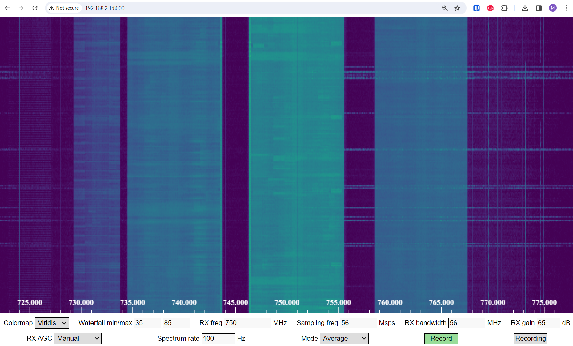
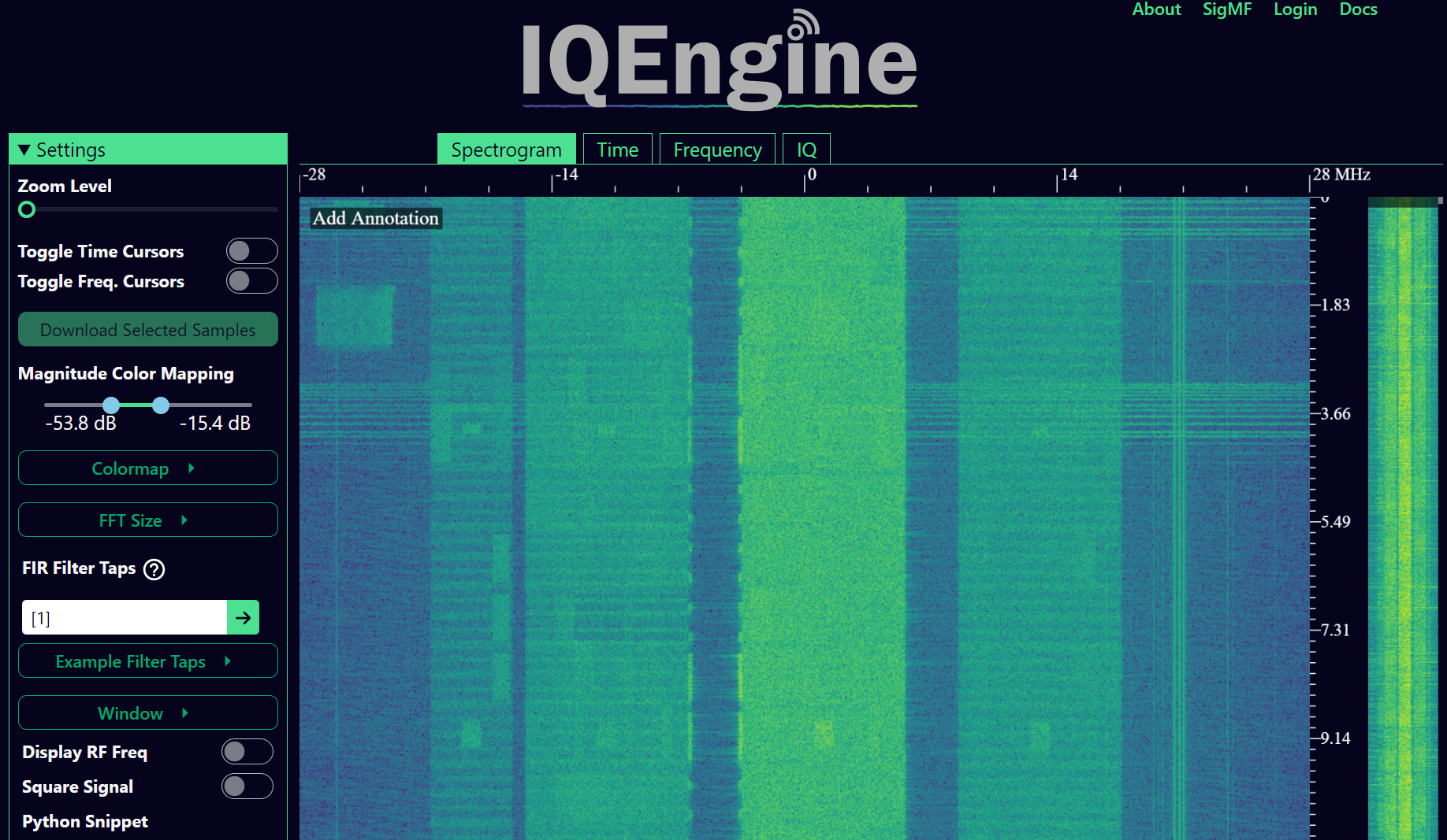
To test how fast Maia can run, try increasing the Spectrum Rate to 100 Hz or more. In addition to controlling the main SDR knobs such as frequency, sample rate, and gain, you can click the Record button at the bottom and it will start recording the raw IQ samples to memory onboard the Pluto. You can then open the recording in IQEngine to view it using the Recording button then View in IQEngine link, as shown in the screenshot below, or save the file to your device.
Reference API
For the entire list of sdr properties and functions you can call, refer to the pyadi-iio Pluto Python code (AD936X).
Python Exercises
Instead of providing you code to run, I have created multiple exercises where 95% of the code is provided and the remaining code is fairly straightforward Python for you to create. The exercises aren’t meant to be difficult. They are missing just enough code to get you to think.
Exercise 1: Determine Your USB Throughput
Let’s try receiving samples from the PlutoSDR, and in the process, see how many samples per second we can push through the USB 2.0 connection.
Your task is to create a Python script that determines the rate samples are received in Python, i.e., count the samples received and keep track of time to figure out the rate. Then, try using different sample_rate’s and buffer_size’s to see how it impacts the highest achievable rate.
Keep in mind, if you receive fewer samples per second than the specified sample_rate, it means you are losing/dropping some fraction of samples, which will likely happen at high sample_rate’s. The Pluto only uses USB 2.0.
The following code will act as a starting point yet contains the instructions you need to accomplish this task.
import numpy as np
import adi
import matplotlib.pyplot as plt
import time

sample_rate = 10e6 # Hz
center_freq = 100e6 # Hz

sdr = adi.Pluto("ip:192.168.2.1")
sdr.sample_rate = int(sample_rate)
sdr.rx_rf_bandwidth = int(sample_rate) # filter cutoff, just set it to the same as sample rate
sdr.rx_lo = int(center_freq)
sdr.rx_buffer_size = 1024 # this is the buffer the Pluto uses to buffer samples
samples = sdr.rx() # receive samples off Pluto
Additionally, in order to time how long something takes, you can use the following code:
start_time = time.time()
# do stuff
end_time = time.time()
print('seconds elapsed:', end_time - start_time)
Here are several hints to get you started.
Hint 1: You’ll need to put the line “samples = sdr.rx()” into a loop that runs many times (e.g., 100 times). You must count how many samples you get each call to sdr.rx() while tracking how much time has elapsed.
Hint 2: Just because you are calculating samples per second, that doesn’t mean you have to perform exactly 1 second’s worth of receiving samples. You can divide the number of samples you received by the amount of time that passed.
Hint 3: Start at sample_rate = 10e6 like the code shows because this rate is way more than USB 2.0 can support. You will be able to see how much data gets through. Then you can tweak rx_buffer_size. Make it a lot larger and see what happens. Once you have a working script and have fiddled with rx_buffer_size, try adjusting sample_rate. Determine how low you have to go until you are able to receive 100% of samples in Python (i.e., sample at a 100% duty cycle).
Hint 4: In your loop where you call sdr.rx(), try to do as little as possible so that it doesn’t add extra delay in execution time. Don’t do anything intensive like print from inside the loop.
As part of this exercise you will get an idea for the max throughput of USB 2.0. You can look up online to verify your findings.
As a bonus, try changing the center_freq and rx_rf_bandwidth to see if it impacts the rate you can receive samples off the Pluto.
Exercise 2: Create a Spectrogram/Waterfall
For this exercise you will create a spectrogram, a.k.a. waterfall, like we learned about at the end of the Frequency Domain chapter. A spectrogram is simply a bunch of FFT’s displayed stacked on top of each other. In other words, it’s an image with one axis representing frequency and the other axis representing time.
In the Frequency Domain chapter we learned the Python code to perform an FFT. For this exercise you can use code snippets from the previous exercise, as well as a little bit of basic Python code.
Hints:
Try setting sdr.rx_buffer_size to the FFT size so that you always perform 1 FFT for each call to sdr.rx().
Build a 2d array to hold all the FFT results where each row is 1 FFT. A 2d array filled with zeros can be created with: np.zeros((num_rows, fft_size)). Access row i of the array with: waterfall_2darray[i,:].
plt.imshow() is a convenient way to display a 2d array. It scales the color automatically.
As a stretch goal, make the spectrogram update live.
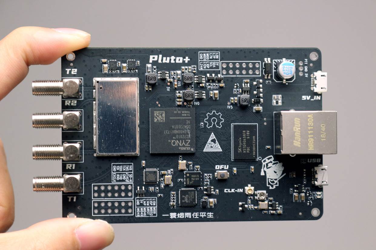
Pluto+
The Pluto+ (a.k.a. Pluto Plus) is an unofficial and upgraded version of the original PlutoSDR, primarily available from Aliexpress. It includes a Gigabit Ethernet port, both RX and both TX channels exposed via SMA, a MicroSD slot, 0.5PPM VCTCXO, and an external clock input via U.FL port on the PCB.
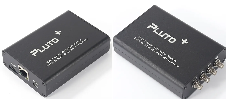
The Ethernet port is an enormous upgrade because it greatly increases the sample rate you can achieve when receiving or transmitting at 100% duty cycle. The Pluto and Pluto+ use 16-bit for I and Q by default, even though it only has a 12-bit ADC, so that’s 4 bytes per IQ sample. Gigabit Ethernet running at 90% efficiency equates to 900 Mb/s or 112.5 MB/s, so at 4 bytes per IQ sample that corresponds to a maximum sample rate of roughly 28 MHz if you want to receive all samples for an extended period of time (e.g., more than one second). As a comparison, USB 3.0 can achieve around 56 MHz, and USB 2.0 is around 5 MHz. There is also a limit to what Python can ingest based on your computer’s power, as well as the specific DSP application you wish to run on the samples (or disk write speed if you are simply recording them to a file). Sample rates closer to 10 MHz are more realistic for Python based SDR applications with the Pluto+ over Ethernet.
To set the IP address for the Ethernet port, plug the Pluto+ in over USB and open the mass storage device, editing config.txt to fill out [USB_ETHERNET]. Cycle power to the Pluto+. You should now be able to SSH into the Pluto+ over Ethernet using the IP you entered. If it worked, you can switch the micro USB cable to the 5V port so that it’s only powering the Pluto+ and forcing all communications to be over Ethernet. Remember that even with the regular PlutoSDR (and Pluto+) you can sample up to 61 MHz worth of bandwidth and get contiguous chunks of up to ~10M samples at a time, as long as you wait in between chunks, allowing for powerful spectrum sensing applications.
The Python code for the Pluto+ will be the same as the PlutoSDR, except you need to swap 192.168.2.1 for the Ethernet IP you set. Try receiving samples in a loop, counting how many you receive, to see how high you can push the sample rate while still receiving roughly the sample rate’s worth of samples in Python per second. As a hint, increasing rx_buffer_size to be very large will help increase the throughput.
